Orifice union fittings hide a precision instrument inside the most boring fitting on the rack: a union body with a drilled disc inside it.
You need one when a line has to pass a fixed, repeatable flow and nothing about that flow is meant to be adjustable. The disc sits in the joint between the union tailpiece and thread piece, published bores run from about .004 in to .125 in, and factory work holds them to ±.0005 in.
That is the short answer. The rest of the page is which bore, and what to put on the RFQ.
Key takeaways
- An orifice union is a union fitting with a precision-drilled orifice plate captured in the joint — the disc sits between the union tailpiece and thread piece.
- Published precision bores run from about .004 in to .125 in, held to ±.0005 in — tolerances a drill press cannot repeat.
- Jobs: limiting flow to instruments, damping pulsation in impulse lines, setting drain and bleed rates, and metering duty on measurement taps.
- Smaller bore means more restriction — lower Cv, higher pressure drop, slower response; size the hole for the job, not the smallest available.
- Do not drill your own: flow through a plain drilled hole can vary as much as 30% hole-to-hole, and edge condition alone changes the coefficient.
Which one do I need?
The decision is not “orifice union, yes or no”. It is what kind of restriction the line is allowed to carry: fixed, adjustable, or shop-made.
| What you are choosing | What it gives you | What it costs you | What actually decides it |
|---|---|---|---|
| Orifice union, fixed | A restriction that cannot drift: no stem, no packing, nothing to loosen | Adjustability — the bore is the setting | The duty is known and will not change |
| Orifice union, replaceable disc | The same fixed bore, with the disc as a stocked spare | One more interface in the joint | The duty might change, or the line cannot wait for an order |
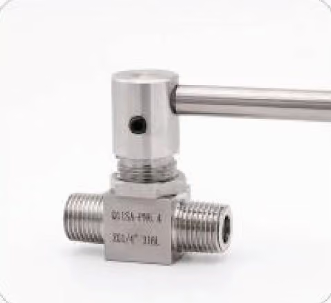
| Needle valve | A restriction the commissioning engineer tunes by hand | A stem seal, and a setting that can walk | The damping setting has to be found on site |
| Hole drilled in-house | A restriction today | Flow varying as much as 30% hole-to-hole, coefficient unknown | Nothing, unless the flow value does not matter |
The union trades adjustability for zero maintenance. No stem, no packing, no adjustment to walk. Specifying the fixed bore is how you buy certainty; specify the needle valve only when the certainty is expected to change.
For fixed, known duties the bored-in-place disc is the cheaper option, with one less leak interface.
What is an orifice union, and where does it go?
Take a standard union — tailpiece, thread piece, nut — and capture a thin orifice plate in the joint between them. The plate is 316 stainless in standard builds, bored to spec or supplied blank, and the union seals around it exactly as it would around a gasket joint.
Maker catalogs describe the same construction across the category: a single-piece plate that fits directly in the union seat and eliminates the separate gasket. That is why the restriction installs and services with ordinary fitting tools, with no spool piece, no flanged orifice run and no special wrench.
For custom bore-and-body combinations, the custom fittings range is the quoting route.
Three instrument-loop jobs dominate, and each is a different reason to put a fixed hole in the line.
Transmitter protection. A differential or gauge device has a maximum working flow through its sensing path, and a restriction upstream caps what the process can push through it. That is the logic that puts a gauge snubber on a Bourdon tube, applied to flow.
Impulse-line damping. Pulsating flows make transmitters chatter, and a restriction in the impulse line averages the pressure the device sees. It is one of the standard damping measures alongside routing, covered in instrument impulse lines.
Rate setting. Bleed lines, seal pots and sampling points that must dribble at a controlled, repeatable rate get there with a fixed bore instead of a hand-valve babysitter.
Measurement duty exists too — a known bore is a known restriction — but that is metering-orifice territory, with its own standards and straight-length requirements. The instrument-line union is about control, not custody transfer.
How do I size the bore?
Sizing language is Cv, the flow coefficient covered in what is Cv. Smaller bore, lower Cv, more restriction for the same pressure drop.
| Bore direction | What it does to the line | Read it as wrong when |
|---|---|---|
| Toward .004 in | Most restriction, lowest Cv, slowest response | The instrument stops seeing real process change |
| Toward .125 in | Lightest restriction, highest Cv, fastest response | The chatter or pulsation is still there |
Catalog ranges give the palette: precision bores from about .004 in up to .125 in, each with a published Cv band. The RFQ line is then simply the job — “cap flow at X under Y conditions”, or “damp a compressor-driven impulse line” — and the bore follows from the maker’s tables.
The working trade-off is symmetric. More restriction damps harder and slows the response; too much restriction leaves the instrument blind to real change. Pick from the flow and pressure conditions, not by habit, because the smallest hole is rarely the right hole.
Below .004 in the territory is specialized micro-drilling. Above .125 in you are usually into a full orifice plate rather than union territory.
Where the duty might change, specify a replaceable-disc union and the bore becomes a spare part instead of a re-order.
What goes wrong, and what do I change?
Most problems on these fittings are selection errors, or a hole that is not the hole on the drawing. The symptom usually names the cause.
| Symptom | Most likely cause | What to change |
|---|---|---|
| Flow is off the drawing, hole to hole | Plain drilled hole: up to 30% spread at identical measured diameter | A factory bore, ±.0005 in, with a verified coefficient |
| Transmitter still chattering | Restriction too light for the pulsation | A smaller bore, or damping in the impulse line itself |
| Instrument slow to follow the process | Bore too small, line over-restricted | Open the bore and trade damping for response |
| Joint weeps after a disc change | Plate not seated in the union seat, or a gasket left in the joint | Single-piece plate against the seat, no separate gasket |
| Cannot retune without a new order | Bored-in-place disc | Replaceable-disc union |
| Quote comes back with the wrong ends | Ends not specified | OD and wall for tube, NPS and schedule for pipe |
You can drill your own, but the hole will not be the size you think. Maker data shows flow through plain drilled holes varying as much as 30% between holes with identical measured diameter; burrs, edge radius and roundness all move the effective coefficient.
Flow-measurement standards require edge sharpness measured in ten-thousandths of the bore. A ±.0005 in factory bore with a verified coefficient is the point of the part; a drill press buys you an unknown.
How do I fit a disc, and how do I swap one?
First fit, in order:
- Read the bore off the disc marking or the order line. The hole is too small to check by eye, so the marking is your record.
- Fit the tailpiece to the line or instrument connection.
- Seat the plate centrally against the tailpiece face. Single-piece, no separate gasket.
- Fit the thread piece so it bears evenly on the plate.
- Run the nut down by hand, then tighten the joint as any union.
On a replaceable-disc union the swap is the same joint broken and remade:
- Isolate and vent the line before breaking the joint.
- Back the nut off and lift the old disc out of the seat.
- Drop the new disc in and remake the joint.
- Leak-check before return to service.
What goes on the RFQ?
Five lines close the specification. Anything missing comes back as a question.
bore— drilled diameter in inches, or “bored to spec” with the flow and pressure conditions.tube or pipe ends— both sides: OD and wall for tube, NPS and schedule for pipe.body and plate material— 316 is the standard plate; body to match the line.service— protection, damping, or rate-setting, with the fluid and its viscosity.replaceable disc— yes or no.
FAQ
Can I drill my own orifice?
You can, but the hole will not be the size you think. Flow through plain drilled holes varies up to 30% hole to hole at identical diameter. A ±.0005 in factory bore with a verified coefficient is the point.
What bore sizes are available?
Published precision bores run about .004 in to .125 in, held to ±.0005 in, and makers will bore outside the table on request. Below .004 in is micro-drilling territory; above .125 in you are into full orifice plates, not unions.
How does the orifice size relate to flow?
Through the Cv relation, the same sizing basis as valves. A smaller bore passes less flow at a given pressure drop, so restriction rises and response slows. Pick the bore from flow and pressure, not by habit.
What is the difference between an orifice union and a snubber?
They share the physics: a small restriction throttling change. A snubber is a damping element ahead of a pressure gauge. An orifice union is a line fitting carrying a fixed, precision bore that sets flow in the line.
When do I need a replaceable disc?
When the duty might change — new pump, different fluid, revised flow — or the line cannot wait for a fittings order. It turns the bore into a stocked spare: pull the nut, swap the disc, remake the joint.