Pipe vs tube is a sizing question that quietly decides whether your fittings fit at all.
Pipe is sized by a nominal name — NPS, Nominal Pipe Size — and its real outside diameter comes from a standard table. Tube is sized by its actual outside diameter and wall thickness. Order on the wrong system and the part that arrives will not match the line on the skid.
Here is the difference and how to state sizes so the quote comes back right.
Key takeaways
- Pipe is sized by Nominal Pipe Size (NPS), and the name is not the measurement: NPS 1/2 pipe actually measures 0.840 inch outside, with the wall set by a schedule number (Sch 40, 80, 160) rather than a simple decimal.
- Tube is sized by actual outside diameter and wall thickness: 1/2 inch tube measures 1/2 inch (12.7 mm) on the OD, and a compression fitting seals by gripping that OD with a ferrule.
- The classic failure is asking for a “1/2 inch fitting” without saying pipe or tube — NPS 1/2 pipe takes a threaded fitting that seals in the thread taper, while 1/2 inch tube takes a compression body that seals on the OD.
- On the RFQ, state tube as OD × wall and pipe as NPS + schedule — two numbers each, and both are needed for a clean quote.
Which one do I need?
The decision is made by what has to seal. A compression fitting seals on the tube’s outside surface, so it is ordered against a measured OD. A threaded pipe fitting seals in the thread taper, so it is ordered against the pipe standard.
| If the line is | Order it as | What actually decides it |
|---|---|---|
| Instrument, hydraulic or small-bore process | Tube: OD × wall — “1/2 inch OD × 0.049 inch wall” | The ferrule has to swage one published OD, and that OD is the fitting’s size number |
| Main process piping, threaded distribution, plumbing | Pipe: NPS + schedule + thread standard — “1/2 inch NPT Sch 80” | The thread taper does the sealing, and the port is cut to the pipe standard |
| High-hazard or severe cyclic service | Welded or flanged family, not threaded | Service decides which joint types are allowed — ASME B31.3 restricts threaded joints |
The table above picks the family. The one below compares the two systems attribute by attribute, and the right-hand column is the part that actually settles an order.
| Aspect | Tube | Pipe | What decides it |
|---|---|---|---|
| Dimension basis | Actual OD — 1/2 inch tube measures 0.500 inch | Nominal (NPS) — NPS 1/2 pipe actually measures 0.840 inch OD | Calipers decide tube size; pipe size is a table lookup, never a measurement |
| Wall spec | Wall thickness as a decimal (e.g. 0.035 inch, 0.049 inch) | Schedule number (Sch 40 / 80 / 160) fixed by NPS + schedule together | Tube wall is ordered as a number; pipe wall follows the schedule, OD across schedules |
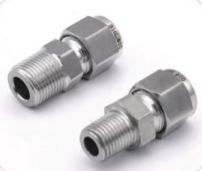
| How the fitting seals | Ferrule grips and seals on the tube OD | Thread taper seals in the threads (NPT or BSPT) | The seal decides the fitting family: ferrule body or threaded body |
| How it is ordered | OD × wall — “1/2 inch × 0.049 inch tube” | NPS + schedule — “1/2 inch Sch 40 pipe” | Two numbers each; one number is an incomplete order |
| Typical duty | Instrumentation, hydraulics, small-bore process lines | Main process piping, threaded distribution, plumbing | The duty decides which joint types the code allows where |
Why does “half inch” mean two different sizes?
The nominal pipe sizes are legacy labels, not measured dimensions. For the small sizes used on instrument and process skids, the NPS name never equals the actual OD. The wall is a second lookup, because each schedule number assigns a different wall to the same NPS.
The actual outside diameter behind each NPS name, for the sizes that dominate instrumentation and process fittings orders, is this:
| NPS | Actual OD (inch) |
|---|---|
| 1/8 | 0.405 |
| 1/4 | 0.540 |
| 1/2 | 0.840 |
| 3/4 | 1.050 |
| 1 | 1.315 |
Two things to read in that table. First, the schedule changes the wall, not the OD: NPS 1/2 Sch 40 and Sch 80 have the same 0.840 inch outside diameter and different walls.
Second, the gap between the two systems is why compression fittings ask for tube OD. The ferrule is engineered to swage one exact diameter, and a pipe-sized guess lands on the wrong part.
Tube walls come in fractional and metric conventions; the near-misses between them are covered in metric vs fractional tube sizes. The pipe thread that does the sealing is explained in NPT vs G (BSP) threads. A printable version of the OD and wall table lives on our pipe schedule chart sheet.
Which fitting does each sizing system take?
A compression fitting for tube grips the OD: the nut drives a ferrule that bites and seals around the tube’s outside surface. The body must be bored for the actual diameter — 12.7 mm for 1/2 inch tube.
A threaded pipe fitting seals in the taper of the thread itself. Its port is sized to the pipe standard, not to any measured inch.
The same logic decides what you can retrofit. Compression fittings join only the tube materials they are rated for, which is why the question gets its own treatment in compression fittings on copper or plastic tubing.
What goes wrong when the systems get mixed?
Most wrong-part orders come from the same few mixes. Each one is visible before the quote if the sizing basis is stated on the line.
| Symptom | Most likely cause | What to change |
|---|---|---|
| Compression fitting will not grip; the nut runs down without swaging | The body was ordered on a pipe name — NPS 1/2 is 0.840 inch OD, not 0.500 | Re-state the line as tube OD × wall |
| Threads engage but the joint weeps at the thread | Wrong thread standard for the port — NPT against BSPT | Add the thread standard to the size: “1/2 inch NPT Sch 80” |
| Ferrule forced onto pipe; the tube deforms or the joint leaks | A compression fitting used on pipe, where the ferrule expects a published tube OD | Use a transition fitting instead of forcing the ferrule |
| Part matches the drawing but not the line | The drawing carried a bare “3/16 inch” with no system named — tube OD against plumbing-copper nominal | Put OD × wall or NPS + schedule on the drawing |
| Replacement pipe has the wrong wall | The schedule was left off; the schedule sets the wall, while the OD stays the same | Add the schedule (40, 80 or 160) |
How do I measure and state the size?
- Measure the outside diameter with calipers. On tube that number is the fitting’s size number. On pipe it is only a cross-check against the table.
- Take the wall thickness with a gauge, or read it from the tubing marking.
- Decide the system before writing anything. Tube for instrumentation, hydraulics and small-bore process lines; pipe for main process piping and threaded distribution.
- Write tube as OD × wall — “6 mm OD × 1.0 mm wall 316 seamless” or “1/2 inch OD × 0.049 inch wall”. The OD selects the ferrule and body; the wall confirms the tube sits within the fitting’s grip range.
- Write pipe as NPS + schedule + thread — “1/2 inch NPT Sch 80”.
That measurement gives you the OD, and that OD is the fitting’s size number. Fittings size by tube OD, never ID, which is why a bare “3/16 inch” on a drawing is a trap — a real 3/16 inch tube OD against plumbing-copper nominal. The size-system rules and the pre-order checks are collected in compression fitting sizes: OD vs ID.
Before the RFQ goes out, check each line against this list — the gaps between the two systems show up as one of these omissions:
- Tube lines carry OD and wall as two separate numbers
- Pipe lines carry NPS, schedule and the thread standard (NPT or BSPT)
- The metric or fractional convention is named, not left to the supplier to infer
- No bare “1/2 inch fitting” line survives review
- No tube size is inferred from a pipe name
A line that says only “need 1/2 inch fittings” costs a round of questions at best. A line with OD × wall or NPS + schedule comes back as a quote.
FerruleX supplies both sides of this table: instrumentation tubing in metric and fractional OD, and compression fittings bored and stamped for the actual tube size.
Send tube OD × wall or NPS + schedule on the RFQ and the quote comes back with the right bodies, ferrules and nuts. Request a factory quote.
How do I join tube to pipe?
With a transition fitting — never by forcing a tube ferrule onto pipe. Three families cover it: a compression male or female connector, a weld-end transition adapter, and a flange adapter.
The compression connector’s tube end grips a true tube OD; its threaded end (NPT or BSPT) screws into the pipe. The weld-end adapter carries a socket- or butt-weld pipe end and a tube end. The flange adapter joins a tube run to a flanged pipe connection. The weld-end families are compared side by side in socket weld vs butt weld fittings.
Which family the code allows depends on service: ASME B31.3 restricts threaded joints by fluid service (para. 314). High-hazard or severe cyclic duty pushes the choice toward the welded and flanged families. Match the pipe end’s pressure class to the pipe rating, not to the tube’s working pressure.
FAQ
What is the difference between pipe and tube?
Pipe is sized by name: an NPS number plus a schedule, with the OD fixed by the standard table (NPS 1/2 = 0.840 inch). Tube is sized by its actual outside diameter and wall thickness.
Is the OD of a pipe the same as its NPS size?
No. NPS 1/8 measures 0.405 inch and NPS 1/2 measures 0.840 inch. Always read pipe OD from the standard table, not from the name.
What does a pipe schedule number mean?
The schedule is the wall-thickness series. For a given NPS each schedule (40, 80, 160) assigns a specific wall, while the OD stays the same. NPS 1/2 Sch 80 is thicker-walled than Sch 40.
Can I use a compression fitting on pipe?
No. The ferrule must grip a published tube OD, and pipe’s OD does not match tube sizes of the same name — NPS 1/2 pipe is 0.840 inch, not 0.500. Pipe is joined by threaded or welded fittings.
How do I measure my tube to find its size?
Measure the outside diameter with calipers and the wall with a gauge or from the tubing marking. State OD × wall on the order. Never infer tube size from a pipe name.
How do I connect tubing to pipe?
With a transition fitting: a compression connector with a threaded end, a weld-end adapter, or a flange adapter. Never force a tube ferrule onto pipe. ASME B31.3 restricts threaded joints by service.