Instrumentation fittings are the precision connectors and valves that join small-bore tubing to process instruments — pressure transmitters, flow meters and analytical devices — in measurement and control systems.
Their job is to hold a gas-tight, leak-tight seal at working pressure while the instrument reads the process accurately. The term covers five families: compression bodies and unions, instrument valves, manifolds, gauge blocks and gauge valves, and tube supports.
Most of them are 316 stainless, chosen for the process environment rather than for pressure alone. Two things then decide the part — the tube OD on the drawing, and the function the point has to perform.
Key takeaways
- Instrumentation fittings are precision components for process measurement and control: they connect small-bore tubing to instruments like pressure, flow and analytical devices, and are built to hold a gas-tight seal at working pressure.
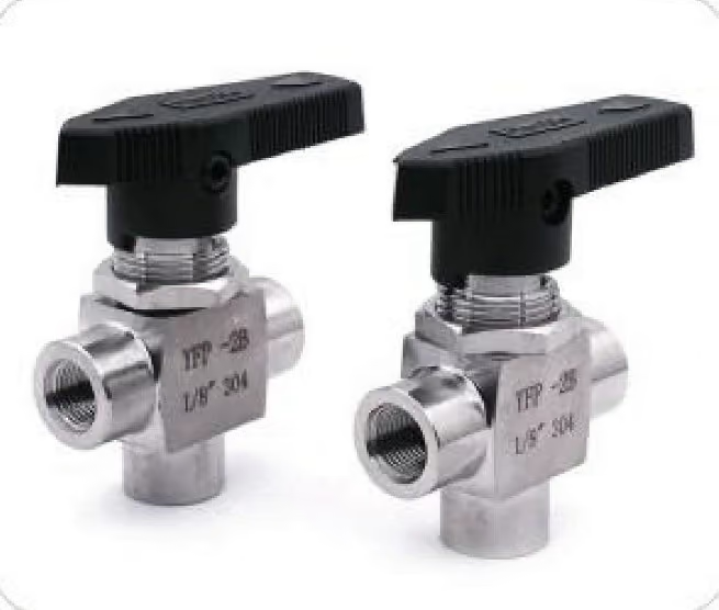
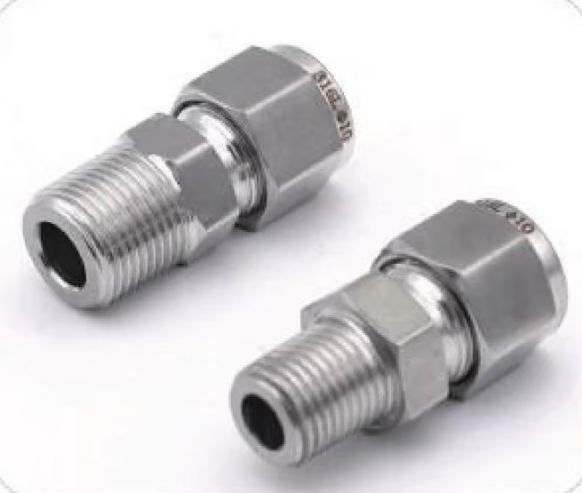
- The families: tube compression bodies and unions; instrument valves (needle, ball, check); manifolds (2-, 3- and 5-valve); gauge blocks and gauge valves; and tube supports.
- They are typically 316 stainless with tight dimensional tolerances because instrument lines carry gas and process fluid where a weep is a failed reading — corrosion resistance and a consistent ferrule seal both start with the material and the machining.
- They are not plumbing fittings: instrument work uses small OD tube, controlled service and leak-tight criteria, while plumbing joins larger pipe for water and drainage — the two are not interchangeable even at matching nominal sizes.
Which one do I need?
The family is set by what the point has to do. Tube size comes after: once the family is fixed, the part number follows the tube OD and wall.
| Family | What it does | Typical service | What actually decides it |
|---|---|---|---|
| Tube compression bodies and unions | Join tube runs and connect tube to ports with a ferrule seal on the OD | Every instrument impulse and supply line | The tube OD and wall — the ferrule seals on actual OD, so the size is the part |
| Instrument valves — ball, needle, check | Shut off, throttle or prevent reverse flow at the instrument | Isolation and vent points, sampling lines | The function at that point: shut-off, throttling or reverse-flow blocking |
| Manifolds — 2-, 3- and 5-valve | Combine block, equalize and vent valves in one body for transmitters | Differential-pressure transmitter hookups | How many functions the hookup needs — isolate only, plus equalization, or plus vent |
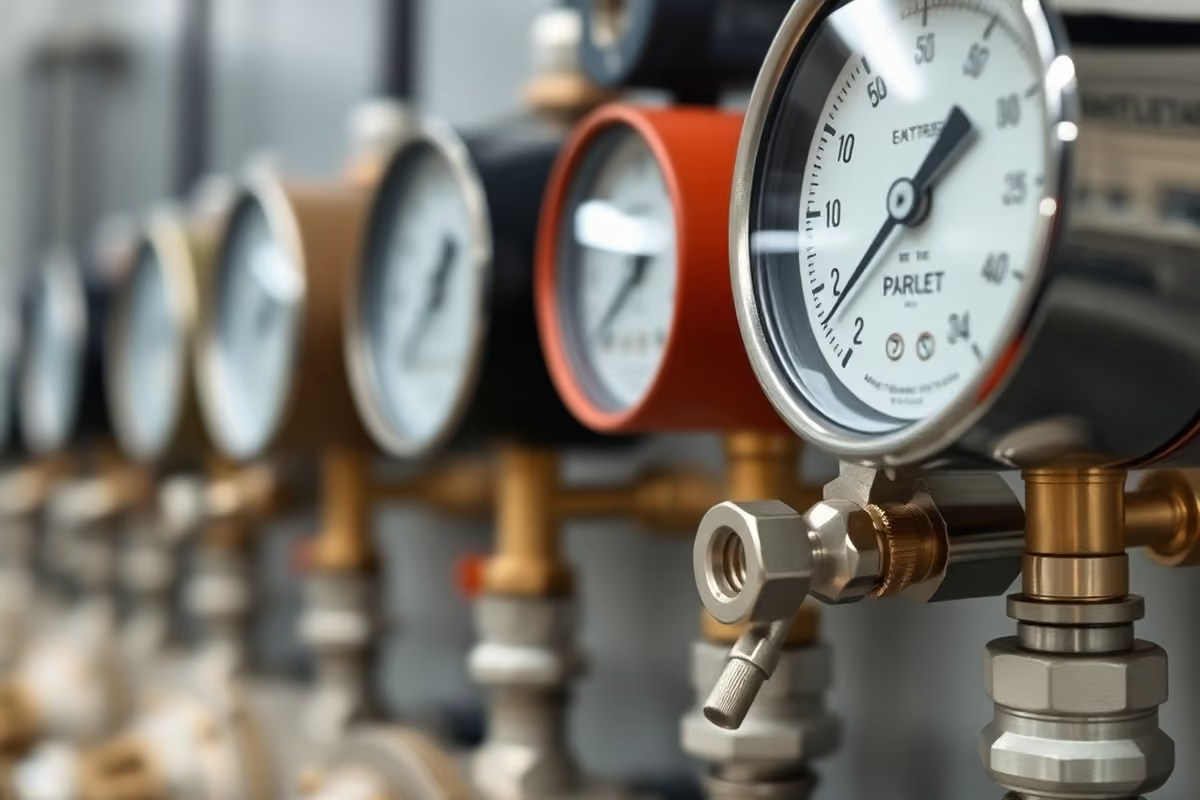
| Gauge blocks and gauge valves | Mount and isolate a pressure gauge or transmitter, with bleed where designed | Local gauge stations | Whether the gauge has to be removed or bled without opening the run |
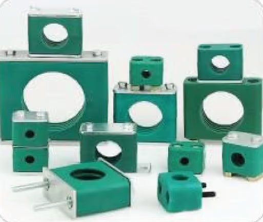
| Tube supports and crossovers | Hold small-bore tube in position and carry lines across panels | Anywhere vibration or movement must be managed | Where the line must not move, and where it crosses a panel |
The manifold row deserves a separate word, because it is where instrumentation fittings most visibly differ from an ordinary valve. What changes is the number of functions built into one body.
A 2-valve manifold isolates and vents a static-pressure instrument. A 3-valve manifold adds equalization for a differential-pressure transmitter. A 5-valve version adds vent ports, so calibration and maintenance happen without breaking the line.
One body replaces several threaded joints — fewer potential leak points on exactly the connections that must never weep. The three configurations have their own catalogue pages: the 2-valve manifold, 3-valve manifold and 5-valve manifold.
How is it different from a plumbing fitting?
The definition sounds close to plumbing. The duty is not, and the difference explains every design choice in the family. Plumbing fittings join larger pipe — water, drainage, building services — with threaded, soldered or push-fit joints sized for flow and convenience.
Instrumentation fittings join small OD tube to instruments under a leak-tight criterion. They are sized by actual tube diameter, machined to close tolerances and tested as a sealed system.
| Aspect | Plumbing fitting | Instrumentation fitting | What actually settles it |
|---|---|---|---|
| Sized by | Pipe nominal size | Actual tube OD | Whether the drawing gives a pipe size or a tube OD |
| Joins | Larger pipe — water, drainage, building services | Small OD tube to an instrument | The line the part has to close |
| Joint | Threaded, soldered or push-fit, sized for flow and convenience | Machined to close tolerances, tested as a sealed system | How the joint is proven tight |
| Failure cost | Water on the floor | A drifting measurement | What the reading is controlling |
A half-inch plumbing elbow and a half-inch instrument compression body share nothing but the words. Different sizing systems, different sealing mechanisms, different failure costs. Even where a nominal size appears to match, the parts are not interchangeable — the instrument fitting’s port, ferrule and pressure rating exist for a duty the plumbing fitting was never designed to meet.
Why 316 stainless and tight tolerances?
Instrument lines fail in a different way from water lines. A joint that weeps a trace of gas does not flood the floor — it drifts the measurement. Gas molecules escape through imperfections water never finds, and analytical instruments turn that contamination into wrong readings.
The material answer is 316 stainless steel, chosen for corrosion resistance across the broad run of process fluids. The machining answer is tight dimensional control, so the ferrule lands exactly where the seal geometry expects it.
That seal logic runs across the whole family. The single- versus double-ferrule choice is the same engineering question, covered in single ferrule vs double ferrule fittings. The tubing the ferrule bites into gets its own treatment in bright annealed tubing.
What goes wrong on an instrument line?
Most field failures are not material failures. They are a joint that sealed against water and not against gas, a part bought against a nominal name, or a hookup missing a function it needed.
| Symptom | Most likely cause | What to change |
|---|---|---|
| Trace weep at a joint that passed a water test | Gas escapes through imperfections water never finds | Re-make the joint so the ferrule lands where the seal geometry expects it; check tube OD and wall |
| Reading drifts after a joint was remade | Tube not sized to the fitting, so the ferrule cannot seat | Replace body and ferrule; match tube OD and wall to the fitting |
| Part will not seal although the size looks right | A plumbing size bought against a nominal name | Buy against actual tube OD — the two sizing systems do not interchange |
| Hookup cannot isolate and equalize separately | A 2-valve manifold on a differential-pressure transmitter | Move to a 3-valve manifold; a 5-valve version where vent ports are needed for calibration |
| Analytical reading wrong with no visible leak | Material or surface not matched to the process fluid | State 316 stainless against the fluid, and put the fluid on the RFQ |
| Joint works loose on a running line | Tube unsupported where movement must be managed | Add tube supports and crossovers at that point |
Anything that drifts a reading is worked as a joint problem or a specification problem first. That is where a trace weep or a wrong-sized part shows up, well before the instrument is suspected.
What does the factory need on the RFQ?
Specifying instrumentation fittings is mostly a statement of tube and duty. Service stated alongside size is what lets the factory match material and rating rather than only dimensions. Build the list in this order and no family goes missing between the tube run and the instrument.
- Step 1 — tube OD and wall. Metric or fractional, as the drawing has it. The ferrule seals on actual OD, so this number carries the seal.
- Step 2 — the service. Gas or process fluid, with the pressure and temperature the line is held at.
- Step 3 — the run families. Compression bodies and unions for the tube runs between points.
- Step 4 — the isolation families. A needle or ball valve at each isolation point, a manifold at each transmitter, gauge blocks at the local gauge stations.
- Step 5 — the supports and the sketch. Supports where the tube must not move, sent with the hookup sketch so the panel reads as one job.
Before the list leaves the office, check each line:
- Every line names a family and a function — a size alone does not order a part
- Tube OD appears in the drawing’s system, metric or fractional
- Wall thickness is written, not inferred from the OD
- Service carries its pressure and temperature, not a fluid name alone
- Isolation points, transmitter manifolds and gauge stations are counted against the sketch
- Supports are listed wherever the tube must not move
FerruleX builds the instrument-panel side of the catalogue: instrumentation tubing in 316 stainless, needle valves for throttling isolation, and check valves for reverse-flow protection. Send the tube OD, the service conditions and the hookup sketch on the RFQ, and we quote the fittings as a panel list. Request a factory quote.
FAQ
What are instrumentation fittings?
Precision components that connect small-bore tubing to instruments in measurement and control systems. They join tube runs, valves and manifolds to devices such as pressure transmitters, flow meters and analysers, and hold a leak-tight seal at working pressure.
What are the main types of instrumentation fittings?
Five families: tube compression bodies and unions; instrument valves (ball, needle and check); manifolds (2-, 3- and 5-valve); gauge blocks and gauge valves; and tube supports. Together they cover the run, the isolation points and the instrument take-offs.
Why are instrumentation fittings made of 316 stainless steel?
For corrosion resistance across a wide range of process fluids and atmospheres. Instrument lines carry gas and analytical samples, where contamination or a weeping joint corrupts the measurement rather than merely wetting the floor.
What is the difference between instrumentation and plumbing fittings?
Sizing, sealing and duty. Instrumentation fittings join small OD tube under a leak-tight criterion; plumbing fittings join larger pipe for water and drainage. They are not interchangeable even where a nominal size matches.
What is a 3-valve manifold used for?
It connects a differential-pressure transmitter to its two impulse lines, with a block valve on each leg and an equalizing valve between them. Isolation, equalization and calibration happen without loosening a tube fitting.