A double block and bleed valve is an isolation arrangement with two independent blocking seals in the same line and a bleed or vent connection between them: close both blocks, open the bleed, and trapped pressure vents while the upstream seal proves itself by holding. It exists to give maintenance a verifiable, depressurized space between the process and the work.
Use it where one leaking seal would endanger people, product or measurement. Single block and bleed is enough where a weeping seat is only a nuisance. Everything below is about which configuration the hazard actually buys.
Key takeaways
- Double block and bleed means two barriers with a bleed between: the bleed vents trapped fluid and proves the upstream seal before anyone opens the line — single block and bleed provides one barrier and no such proof.
- The term carries two definitions: API 6D defines a DBB valve as one valve with two seating surfaces sealing against pressure from both ends plus a cavity bleed; OSHA-style practice means two separate closed valves with an open vent between them.
- Instrument-scale DBB duty — gauge and transmitter isolation, sampling, calibration — is commonly built from needle valves, manifolds and bleed vents rather than pipeline trunnion ball valves.
- DBB is practice born of risk assessment, not a universal regulation: the hazard, the site standard and the permit decide — specify barriers and bleed routing, not just the acronym.
Which one do I need?
The choice turns on what a leak past one seal would do, not on the label on the valve. A single block and bleed gives one barrier and a vent. Double block and bleed gives two barriers with a proving volume between them.
| Configuration | Seals | Bleed function | Typical duty | Decisive — what actually decides it |
|---|---|---|---|---|
| Single block and bleed | One isolation seal | Vents instrument side; may reveal seat leak | Low-risk gauge isolation, utility vents | Consequence of one weeping seat — a nuisance, not a hazard |
| Double block and bleed (two valves) | Two independent seals | Vents and monitors the cavity between barriers | Gauge and transmitter isolation on hazardous lines; sampling and injection points | One leaking seal would endanger people, product or measurement |
| Double block and bleed (single API 6D valve) | Two seating surfaces in one body | Cavity bleed; no positive double isolation under one-sided pressure | Pipeline and process isolation, space saving | Whether the spec accepts the standard’s own caveat on one-sided pressure |
| Double isolation and bleed (DIB) | Two seats, each sealing one source direction | Cavity relief via external means | Highest-integrity isolation, either barrier must hold alone | Sour or critical service needing a provable single barrier |
One caution from the API definitions: a single-valve DBB seals against pressure from both ends but, by the standard’s own note, not under one-sided pressure. For true two-barrier isolation there, the two-valve arrangement or a DIB valve is the honest answer.
This is also why the term clusters around instrumentation manifolds, where block, equalize and vent functions share one body.
DBB is practice born of risk assessment, not a blanket regulation. OSHA’s confined-space rule lists double block and bleed among accepted isolation methods, and API 6D defines the valve configurations, but neither makes it mandatory at every instrument.
The deciding questions are the hazard of the media, the consequence of an undetected seat leak, and the site or permit standard. Answer those three and the configuration is settled.
Where does instrument duty use it?
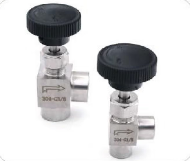
The instrument-panel version is smaller than the pipeline version and usually assembled from catalog parts: a needle valve per block, a compression fitting or manifold port as the bleed.
| Duty | Why DBB | Alternative | Decisive factor |
|---|---|---|---|
| Pressure gauge isolation on hazardous media | A weeping seat puts process fluid on the gauge; the bleed vents and proves | Single block and bleed for benign media | Hazard of the media |
| Transmitter calibration and removal | Trapped loop pressure vents through the bleed; second barrier protects the live process | Manifold with integral block and vent valves | Whether the line stays live while the instrument comes off |
| Sampling and injection points | Cavity bleed confirms seal integrity before the sample point opens | Single valve with downstream purge | Whether a bad sample or a leak costs more |
| Custody-transfer and prover connections | Prevents bypass leakage around the prover that corrupts measurement | Blinds and spools where line breaking is acceptable | Whether the measurement error is billable |
The oil and gas context where this duty concentrates is covered on the oil & gas instrumentation page.
How do I assemble one?
An assembled instrument DBB is two blocks, one bleed and a drawing. The bleed has to sit between the barriers, or it proves nothing.
- Step 1 — set the barrier count. Two blocks where one weeping seat endangers people, product or measurement; one where it does not.
- Step 2 — choose the blocks. A needle valve per block, sized for the line, with the seat chosen for the media.
- Step 3 — place the bleed. Between the two blocks, never downstream of both: the cavity between the barriers is the volume that gets proved.
- Step 4 — pick the vent part. An instrument bleed valve for a tell-tale vent, or a manifold vent port where the assembly is a manifold.
- Step 5 — mark the sketch. Which valve is upstream, which is downstream, which is the bleed, and where the bleed drains.
How do I isolate with it?
The sequence is the reason the third connection exists. It is short, and the order is what makes the result proof rather than assumption.
- Step 1 — close the upstream block. The process side is sealed at the first barrier.
- Step 2 — close the downstream block. The cavity now sits between two closed seals, and its volume is what the bleed will empty.
- Step 3 — open the bleed. Trapped pressure vents through the drain or vent the bleed is routed to.
- Step 4 — watch the bleed. Continued flow means the upstream seal is passing; the barrier is not proved and the work does not start.
- Step 5 — break the downstream side. Only when the bleed is dry and stays dry does the gauge, transmitter or sample point come off.
What fails, and what do I change?
Most faults show up at the bleed, which is what the arrangement is built to do. Read the symptom there first.
| Symptom | Most likely cause | What to change |
|---|---|---|
| Fluid appears at the bleed after both blocks are closed | The upstream seat is passing | Reseat or replace the upstream block; go to a DIB arrangement where that seal must hold alone |
| Gauge still reads pressure after both blocks are closed and bled | The bleed sits downstream of both blocks instead of in the cavity between them | Move the bleed between the barriers — that cavity is the proving volume |
| Arrangement looks doubled but one-sided pressure still reaches the work | A single API 6D valve: two seats sealing against pressure from both ends, not from one side only | Use two separate valves, or a DIB valve for provable isolation |
| Instrument side pressurises from back-flow when the bleed is shut | No back-flow protection in the arrangement | Add a compression check valve, or a manifold block that carries one |
| Second barrier carries no maintenance argument on a benign line | Single block and bleed duty was over-specified | Drop to one block and bleed; spend the second barrier where the hazard is |
What should go on the RFQ?
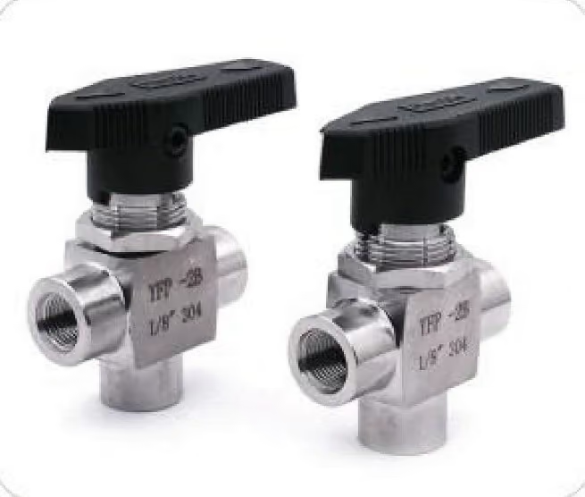
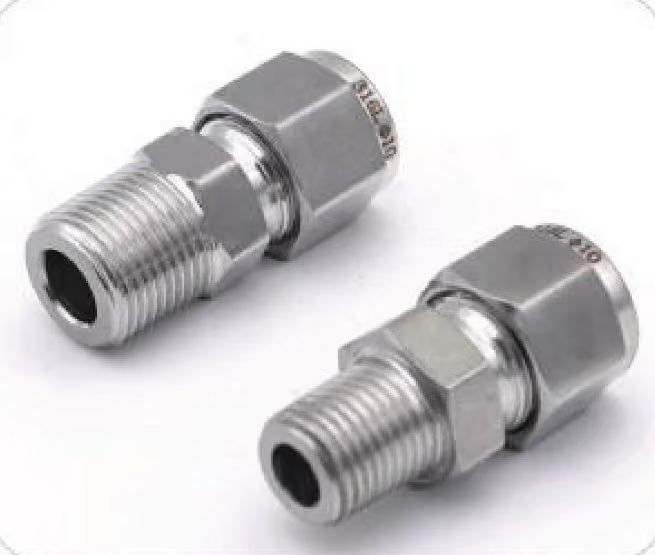
We do not build a dedicated DBB valve line, and we will not pretend a catalog single valve is a double barrier. What we quote is assembled from existing parts: needle valves as the blocks, compression check valves where back-flow protection matters, and compression unions or manifold ports as the bleed.
For instrument-side duty the manifold line already carries two-barrier configurations. The 3-valve manifold and 5-valve manifold pair block valves with an integral vent or drain between them. An instrument bleed valve supplies the tell-tale vent for assembled two-valve arrangements.
If the duty needs a single certified DIB valve, that belongs to a pipeline valve catalog. We will say so rather than stretch a needle valve into a standard it does not meet.
Send the hookup sketch with these points settled:
- Barrier count: one block or two, and what decides it
- Bleed position: between the barriers, and where it drains
- Line size and thread: for example two needle valves with bleed between, 1/2 NPT process, 316
- Seat and body material for the media
- Back-flow protection: needed or not
- Upstream and downstream marked on the sketch
FAQ
When is double block and bleed required? When one leaking seal would endanger people, product or measurement and the work needs provable isolation: hazardous media, sampling points, gauge and transmitter work on live process. The trigger is the risk assessment and the site standard.
What is the bleed valve function? It vents the cavity between the two closed blocks to atmosphere or a safe drain. That releases trapped pressure before the line opens, and continued flow there tells the operator the upstream seal is passing.
Can a single valve be a double block and bleed? Under API 6D, in a limited sense: one valve with two seating surfaces that seal against pressure from both ends, plus a cavity bleed. The same standard notes it gives no positive double isolation under one-sided pressure.
What is a block and bleed valve for a pressure gauge? A block valve between process and gauge, and a bleed that vents the gauge side. Single block and bleed suits benign media; double block and bleed where the process is hazardous and the seat must be provable first.
Do I need a special DBB valve for instrument panels? Usually not. Instrument-scale DBB is commonly assembled from a needle valve per block plus a bleed fitting or manifold port, routed per the hookup drawing — serviceable, and honest about what each component is.