Flanged connections are bolted joints: four bolts on a standard pattern hold a small valve in the run, replacing the thread as the attachment. A flange changes how the valve is held in the line, not what it does in service. The choice rests on whether the valve will ever need to come out, then on three lines: rating, face, bolting.
Key takeaways
- Flanges buy break-in maintenance: the valve unbolts and slides out without cutting pipe — the reason flanged ends exist at mid sizes.
- Class 150 sits at roughly 19.6 bar at ambient; its dimensional EN 1092-1 equivalent is PN 20, while PN 16 is the pressure-nearest common valve rating — the two cross-walks are different claims.
- Class 150 and PN 16 bolt circles differ in most sizes; direct inter-bolting is not endorsed, some sizes field-mate, and dual-drilled conversion flanges are the clean bridge.
- RF (raised face) seats a ring gasket at high stress; FF (flat face) spreads load full-face and exists for brittle flanges like cast iron.
- Stainless practice: flange matches line material, and zinc-plated bolts against stainless flanges are a galvanic cell the moment moisture arrives.
Flanged or threaded — which do I need?
The case for flanges is the outage it prevents. A threaded valve in a fixed run cannot be unscrewed in place: threads unwind in one direction, and the pipe on both sides refuses to move.
Removal means cutting, and cutting means re-welding or re-threading both ends of a spool. The flange comparison literature states the contrast plainly: unbolt, slide out, bolt in the new valve, done in minutes with standard tools.
| Threaded end | Flanged end | What actually decides it | |
|---|---|---|---|
| Removal for service | Cut the spool, then re-weld or re-thread both ends | Unbolt, slide the valve out, bolt in the replacement | Whether the valve will ever leave the line |
| Tools on site | Welding or threading equipment | Standard hand tools | What maintenance actually carries |
| Cost per valve | Lower | Higher, repaid at the first removal | How many removals the run will see |
| Small-bore range | Throughout | Ball and gate valves from DN15 to DN50 and beyond | Whether the size is catalogued flanged |
That is the whole economics: flanged ends cost more per valve and repay it the first time maintenance does not need a hot-work permit. On small bore the pattern holds, with flanged-end ball and gate valves running commonly from DN15 to DN50 and beyond.
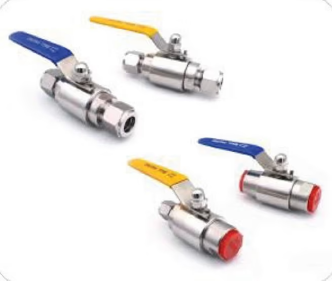
The flange answers nothing about which valve goes inside it. A gate valve seals by wedging a gate across the bore and must never be throttled; a ball valve turns a quarter turn against seats. The isolation-duty trade-off between them, including how each fails as it ages, is covered in gate valve vs ball valve.
The swap itself, once both ends are flanged, is five moves:
- Step 1 — isolate and drain the run.
- Step 2 — unbolt the four bolts and lift them clear.
- Step 3 — slide the valve out axially; no pipe moves.
- Step 4 — fit the replacement with a gasket of the form its face takes.
- Step 5 — bolt up on the same pattern and check facing and gasket alignment before the line returns to service.
What do Class 150 and PN 16 actually mean?
Class and PN are two rating systems that converge without matching. The published cross-walk: Class 150 pairs dimensionally with PN 20, Class 300 with PN 50. ISO 7005 flanges are designed to be interchangeable with ASME B16.5 drillings at those pairs — deemed to comply, without being identical.
On pressure capacity, Class 150 carries about 19.6 bar at ambient against PN 16’s 16 bar, which is why “Class 150 ≈ PN 16” circulates.
PN 16 is the pressure-nearest common valve rating; PN 20 is the dimensional flange equivalent. Keep the two claims apart and the RFQ stays clean: name the flange standard and class, or the EN 1092-1 standard and PN, and let the other system ride the cross-walk.
| Class 150 | PN 16 | What actually decides it | |
|---|---|---|---|
| What the number states | An ASME pressure-temperature rating class | A European nominal-pressure rating, 16 bar at the 20 °C reference | Which system the rest of the line is drawn in |
| Pressure at ambient | About 19.6 bar | 16 bar | The higher figure does not make the two flanges inter-mate |
| Dimensional EN 1092-1 equivalent | PN 20 | Not a Class 150 dimensional match | PN 20 is the flange cross-walk, PN 16 the valve-rating cross-walk |
The vocabulary groundwork is laid in the RFQ glossary, and the pressure-side semantics in proof pressure vs burst pressure.
Which face — RF or FF?
The face decides how the gasket works. A raised face concentrates bolt load on a small annulus, seating a ring or spiral-wound gasket at high sealing stress with modest torque — the default for steel flanges. A flat face spreads the load across the whole surface with a full-face gasket whose bolt holes align with the pattern. It exists for one reason: brittle flanges.
Bolt a cast-iron FF flange against a steel RF flange, and the raised nose carries the reaction as a bending moment on a material with no ductility; the casting cracks. The rule the references state as not negotiable is that grey cast iron demands flat-face to flat-face. Pair like with like, and RF-to-RF remains the stainless default.
| RF, raised face | FF, flat face | What actually decides it | |
|---|---|---|---|
| Gasket form | Ring or spiral-wound, seated on a small annulus | Full-face, bolt holes aligned to the pattern | The gasket the joint is designed around |
| Bolt load | Concentrated on the annulus, high sealing stress at modest torque | Spread across the whole face | Whether the mating flange can take point load |
| Mating flange | Steel and stainless, the default | Brittle flanges, grey cast iron above all | Ductility of the flange the joint lands on |
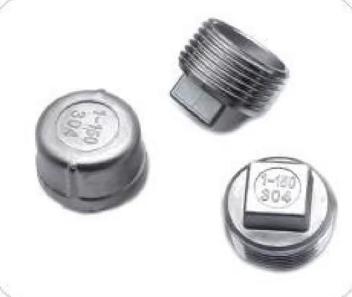
The flanged members of our plug range carry the same face logic at the port-closure end: the flanged hex socket plug and the flanged hex head plug.
What keeps a stainless joint sound?
Two practices keep stainless flanged joints honest. The first is material: the flange matches the line. Standards practice for stainless piping specifies flanges and fittings of the same material and grade as the pipe they attach to — 316 line, 316 flange.
The second is bolting. Zinc-plated or plain carbon-steel bolts against stainless flanges are a galvanic couple waiting for an electrolyte, and humid air qualifies. The references put zinc ten positions below stainless on the galvanic series and the zinc sacrificial, which reads in the plant as corroding fasteners and seized joints.
Stainless bolting against stainless flanges is the default. Where mixed bolting is unavoidable, decide it with the dissimilar-metal rules in galvanic corrosion in mixed fittings.
What goes wrong, and what do I change?
Most failures on small-bore flanged joints come from one of three mismatches: face against material, bolting against flange, or two rating systems bolted together.
| Symptom | Most likely cause | What to change |
|---|---|---|
| Fasteners corrode and the joint seizes | Zinc-plated or plain carbon bolts against a stainless flange, with humid air as the electrolyte | Stainless bolting, or a coating and isolation plan decided on the dissimilar-metal rules |
| Cast-iron flange cracks at the bolt holes | An RF nose bearing on an FF casting, so the reaction arrives as a bending moment the material cannot take | Flat-face to flat-face, full-face gasket, no raised nose in the stack |
| Joint weeps at modest torque | Gasket form does not match the face | Ring or spiral-wound on RF, full-face on FF |
| Bolts will not pass through the mating holes | Class 150 against PN 16, whose bolt circles differ in most sizes | A dual-drilled conversion flange, or stay inside one flange system |
| Valve cannot leave the line without cutting | Threaded end in a fixed run | Flanged end at the next spool change |
How do I specify a flanged small valve?
One system per flange. Give size and rating together, name the facing, and the rest follows from the line.
- Step 1 — pick the system. ASME class or EN PN, one per flange.
- Step 2 — give size and rating as one line.
DN25, PN16or1 in, Class 150. - Step 3 — state the facing. RF or FF, plus the gasket standard where it matters.
- Step 4 — give the material as a grade that matches the line. 316 line, 316 flange.
- Step 5 — state the bolting. Stainless, or the coating and isolation plan.
Before the RFQ leaves:
- Rating written in one system, ASME class or EN PN
- Size and rating on the same line
- Facing named, RF or FF
- Gasket standard stated where it matters
- Flange grade matched to the line grade
- Bolting stated, stainless or coated with an isolation plan
- Mating flange material known, so the face can be checked against it
FAQ
Can I mate a Class 150 flange with a PN 16 flange?
Not directly. The ratings are near-neighbours — about 19.6 bar against 16 at ambient — but bolt circles differ in most sizes, and direct inter-bolting fails on drilling mismatch. A dual-drilled conversion flange is the clean bridge.
What is the difference between Class 150 and PN 16?
Class 150 is an ASME rating class: about 19.6 bar at ambient, falling with temperature. PN 16 is a European nominal-pressure rating of 16 bar at the 20 °C reference. PN 20, not PN 16, is the dimensional EN equivalent.
RF or FF face — which do I need?
RF for steel and stainless: a ring gasket on the raised face. FF for brittle flanges — grey cast iron above all — where a full-face gasket spreads the load. Match the face to the mating flange.
What size do flanged small valves start at?
Commonly DN15, running through DN50 and beyond; flanged-end ball and gate valves are catalogued from half-inch nominal. DN8 and DN10 flanges are reserved for special instrument and regulator patterns.
Can I use galvanized bolts on stainless flanges?
Only in genuinely dry service. Zinc sits ten positions below stainless on the galvanic series, so a coated fastener becomes the sacrificial anode once an electrolyte appears — and humid air is electrolyte enough. Stainless bolting is the default.